Showing posts with label Automata-DiggerBot. Show all posts

Sunday, November 7, 2010

AUTOMATA - "DiggerBot" FINISHED!

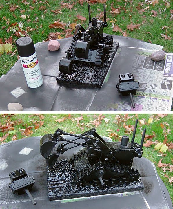
This little guy is finally done!!! The DiggerBot was way more involved to build than I originally anticipated. I had lost steam for this "steam-punk" project several times. But today I went out for some location shots at a construction site, and am actually smiling at the results. There's not going to be a lot of commentary on the paint job...just enjoy the photos!

I wanted to show the earliest stage of when I began to paint the Bot. I was really torn as to what color to go with, once I had sprayed on a primer coat of black. It reminded me of an old black train locomotive...and I really liked that look. I came really close to just hitting it with some silver on a few details, and calling it "done".
I also like the yellow colors of modern construction equipment. In the end, I went with a worn-out ol' rust-bucket bronze-red. Below are the basic arm movements. Unfortunately, the crank mechanism ended up being tighter to turn (due to the paint), so there's a bit of effort required to bring it to life.

So that's it for the latest project. Might have to get some more shelves!

Sunday, October 24, 2010

AUTOMATA - "DiggerBot" Pt.8

The detailing is done...all ready for the paint job! But that'll have to wait for next time. Let's take a look at the final additions.

I made the "tank tracks" from lots and lots of pieces of cut bass-wood, and stuck them on with wood glue. I also added some more little "wheels" on the sides. I also added some support "hydraulics" for the main digger arms.

Next came the rivets. I used a small hole punch on some "peel and stick" foam rubber. Then came the "fun" of meticulously placing each one on the Bot with tiny pliers. Some of the sticky-back stuff wasn't holding, so I had to dip some of the rivets in super-glue, then stuck them on. The black foam won't stay that color...it will all be painted over.

Here's the back view of the boiler, and of the front grill. Once I had all the rivets in place, I painted everything with wood glue, to give a harder surface to the spongy soft foam. It also unifies the surfaces, and gives some "aging" texture to the very smooth wood.

Now comes an experiment that sort of worked...but was a huge mess. To create some lightweight "dirt", I tried using an old blender to chop up some packing foam peanuts. The chopping part worked fine...the static cling made little bits of foam go everywhere and stick to everything! I had originally wanted to use a heavier weight, denser pink insulation foam, but did not have any. I took the little chunks, mixed them with wood glue, then applied them to the front of the base.

To complete the "dirt" effect, I added sand to gesso, then painted all of the ground surfaces, as well as coating the chunks of styrofoam.

The gesso-sand helps pull everything together. Once it's painted, it will look just like real dirt!

One more shot of the back view.

On a side note...just letting you know that it will be a while before I can finish the final paint job. Next weekend, my brother is coming for a visit so that we can go see the Roger Waters Concert in Kansas City on Oct. 30th! They will be playing Pink Floyd's "The Wall", and the reviews have been awesome!

Sunday, October 17, 2010

AUTOMATA - "DiggerBot" Pt.7

Here's your base-model DiggerBot...no radio, no air-conditioning, no power-steering. I spent most of the weekend on this project, and am so glad to have finally gotten to this stage! Now that the basic automata works, I move on to the fun part of adding the "steam-punk" elements like rivets and more details. After that...the finished paint job!

Let's take a look at the new added-on bits since my last post. I needed to give a little more stability to the gear-box, so I made some framing in the front. Next I glued on the stationary "shoulders" part of the digging arms. In the back, I added the piece that holds the dowel that will allow the head to move up and down. The larger dowel acts as a "neck", and keeps the smaller dowel from going crooked, as it moves.

Here are all the parts that go together for the head. Underneath, I have drilled a hole large enough to fit around the "neck", and also the hole for the dowel. I wish I was a better craftsman with making all of these parts...nothing is squared up, and looks very "hand-done". (How about we just say it "adds charm" that way? There I feel much better.)

One adjustment to my original idea for the head movement...I added a little peg near the neck piece, so that the head would have a slight turn towards the person cranking the handle. Before that, the head was loosely turning all around, and looked a bit goofy.

After the head was done, I started to box everything in, and created the form of the outer body. I also added some more wheels on the sides.

The last piece to make was the boiler tank with double exhaust pipes. This view is of the inverted DiggerBot...I turned it this way to keep the tank from sliding as the glue dried. As I look at the photo now, it reminds me of one of those two-legged walker machines from Star Wars. Hmmm...ideas for later, perhaps?
Here are a few more shots of the semi-finished DiggerBot. Next time, I'll be making piles of "dirt" for the base, completing the tank tracks, and adding more "doo-dads" all over.

Thursday, October 7, 2010

AUTOMATA - "DiggerBot" Pt.6

Looks like I'm finally making some progress on this project. I have to say, this week was very challenging to keep my enthusiasm up. Lots of technical issues arose...but once I figured out how to work around them, my momentum picked up again. So...what did I get done since last time?

First off, I managed to assemble most of the parts for the digging arms. Now they're ready to be attached, once I get farther along on the other bits.

Here's where things started to bog down...making some gears. I drew up some plans on the computer, spray-mounted them to a 2x4, then cut them out on the band saw (one tiny tooth at a time). I tried some small triangular teeth first...took quite a while to do. But I soon found out that precision measuring and cutting are really crucial...not my strong points.

After failing at different variations, I finally found a website that had a little gizmo on it that lets you custom design patterns for gears. The larger teeth seemed like it would work better. Also, I decided not to make the gears so wide (from the 2x4 width) and used some half-inch hardwood board.

Here's the final version, and a little "gear box" that holds it all together. I've added the circular attachments where the digging arms will go 'round and 'round. The smaller gear at the bottom has the axle going through it that will be part of the hand-crank mechanism.

I then constructed some "cams" that will rotate on the axle, and push a "paddle/lever" up and down. This is what will cause the DiggerBot's mouth to open and close (by pushing a dowel rod to be added later). I shortened the paddle a bit from what you see below.

Finally, I made the "tank tracks" shapes that supports the gear-box. I will do a lot more detailing on those later...just wanted to get the main structure built. I'm still having some problems with the gears hanging up a bit, when I crank the handle. Hopefully, I'll be able to adjust some things later to fix that.
Okay...that's it for now...my head hurts from too much thinking this week!

Saturday, September 25, 2010

AUTOMATA - "DiggerBot" Pt.5

Well, there's not much to show this week, except a messy workbench. But I do have some sketches of "problem solving". There were design issues that I had not yet figured out, so I needed to do some thinking on paper before I spent more efforts in wood.

One of the things I decided to add to the movements was the DiggerBot's mouth opening and closing. I had considered using a string or wire, which would pull on a hinge...but ended up with a simpler idea. The weight of the head will press down to keep the mouth closed. But a dowel in the neck will be pushed upwards by a lever, and gravity will pull the jaw open, as the head goes up.

I had cut out a more organic shape for the larger support arm. Originally the flat side was on the left, like an "L" (see sketch above). But I looked at modern diggers, and flipping the "L" was more like today's style. I had also made a circular end-piece for the lower arm. I now prefer the way I did the upper arm, so I'll have to modify them.

Once I had flipped the "L" shape, I was wondering about some other embellishments. On a modern digger, there are hydraulic arms that push and pull the main arm. Mine will be just for looks, since the support arm will be glued stationary.

Next, I just started sketching some variations on proportions and design. As I was working on some of the bits and pieces, my original prototype model started malfunctioning a bit. The earlier "belt drive" began to slip some, and the cranking motion wasn't working consistently. So I got a little concerned that my final version would have "issues". So I began to consider a gear driven mechanism. It seemed like it would be sturdier, and more dependable. I also spent a little time figuring out the cam-driven lever that would make the head go up and down.

It didn't take long before I was again handicapped by my lack of engineering skills. So I started sketching around with how I'm gonna make these wooden gears. Luckily, YouTube.com has some demos from woodworkers to give me some help.


So this last page has the basic gear-drive in place. I also thought that I should flip the triangular "tank tracks" around, more like early World War I versions. This approach would let me hide a second gear underneath, which would now become the axle used for the crank handle. The early model had a gear-box underneath...this way I can let the DiggerBot rest on a single base of wood.
That's it for this time...hopefully I'll make some progress on the construction next week. (I have to be honest here...this is moving slower than I want, and is not as much "fun" at this stage. I know I'll enjoy painting this guy...but that's a long way off. )

Saturday, September 11, 2010

AUTOMATA - "DiggerBot" Pt.4

I'm making some progress on the final "DiggerBot" parts. Here is how I made the bucket and arms.

I used the flat bucket shape from the prototype model as a template, then traced it onto a piece of 2"x4". I added a bit of length to the front of the bucket for the "teeth". Then cut it out with my band saw, and sanded it smooth on a belt sander.


Next I cut out the sides of the bucket from some bass wood, then glued them onto the bucket.

I had to modify the bucket a bit to allow for the full range of motion when connected to the arms. I had not accounted for this problem with the flat bucket model. So I cut out a section, then glued on a little extension, drilled it and sanded to the circular shape.

Here's how I made the "couplings" that go on the dowels for the arms. You may note that nothing is exactly squared-up and precise. I don't think I can do that if I tried...I definitely show the "hand of the artist" on these projects. Adding the paint job at the end hides a lot of those imperfections.

Here is how this new bucket will move. The lower arm is probably going to look different than what is shown here, but you get the basic idea.

Sunday, September 5, 2010

AUTOMATA - "DiggerBot" Pt.3

Welcome back to the "DiggerBot" in process. It's nice to have a long Labor Day weekend to work on this a bit more. Above is the two-armed prototype that I made to help me figure out some more of the mechanical components. I will change this quite a bit later, design-wise...but it was very helpful to build a rough version.

I'd like to take a brief moment to give some credit to my Mom's "sketchin' buddy", APRIL, for sending me some ideas to improve the engineering of the arm movements. It's been fun collaborating with someone who has a better brain than mine for these things. Thanks, April!

Below are the bits that make up the "bike pedal" action for the top axle. The Bot-arms will attach to this part. I like to use dowel pegs and a bit of Elmer's wood glue, instead of nails and screws, to put all of this together. The tight fitting pegs will hold things in place until I'm sure things work.


I temporarily attached the arm bits, to see if the axle rotation produces the effect I want.

Next, I made the gear box, so I can figure out the drive mechanism that will be underneath. I had to add a little block of wood to the base of the axle housing, because I had cut off too much earlier. These things happen. Again...this is quick and dirty, just for figuring out if this will really function.

Now you'll see the series of "failures" before I found a workable solution. My first idea was to use one of my daughter's "ponytail holders" to attach to the drive shaft underneath. Too stretchy...not enough tension. Next I tried a bit of twine, since it was rougher. But it slipped on the wood axles. So I ground in some grooves with my dremmel tool. Still didn't work. Then I made a little "cuff" of sticky-backed foam rubber. That seemed to help. I then made a larger "gear" for the lower drive shaft, to give more tension...the string still slipped on that, too. Finally I added some foam to the gear...it worked! Sort of...the string would slide off the rubber part and snag up on the sides of the axles.

Finally, I thought of making a true "belt drive" for this. I had some "fake leather" material, cut a long strip the right length...super-glued the ends together...and added a little duct tape for good measure. Worked just right!!

I made a duplicate arm for the opposite side of the Prototype TestBot, and...VOILA!
Things will slow down a bit from here on, because I will be designing more complex shapes for the final "DiggerBot". I'm also thinking about adding some other moving parts (like the Bot's mouth opening and closing). Stay tuned!!